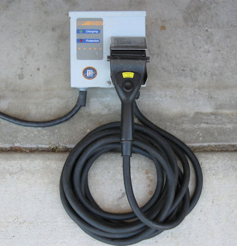
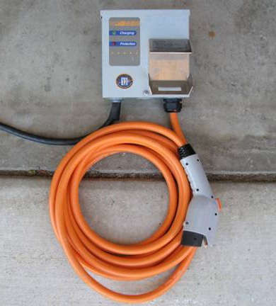
Steps to put a new J1772 format Electric Vehicle Connector on an EVI DS-50 Charging Station. |
||
Background: The EVI-DS-50 charging station was one of the most popular EV charging stations (now called “Electric Vehicle Service Equipment” or “EVSE”), and came equipped with the old “Avcon” EV connector that was standard in 2001. There are not that many vehicles which are in service today that use the Avcon connector, but the EVI DS-50 electronics conform to the new (2010) J1772 standards so they can be re-used. |
||
Other |
Turn this |
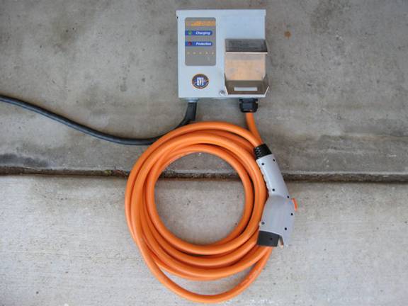
into this..... |
Putting a new plug and cord set on the DS-50 is relatively easy and can yield a good charging station for considerably less money than purchasing a new charging station. |
||
Step 1 - Turn off the power to the charging station
Open the front panel by removing the single screw at the bottom of the panel, and remove the front panel. Be careful with the wires that are still attached to the front panel LEDs. Check to see that the “diagnostic” (heartbeat) LED on the circuit board is not on or flashing, just to make sure that the power is really off. |
 |
|
Step 2 - Cut the small Blue wire, leaving enough wire connected to the circuit board to allow the new wire to be spliced to it. Strip about 3/8 of an inch of insulation from the Blue wire that’s attached to the circuit board - you’ll be connecting a wire to this later. |
 |
|
Note that the Black and Red wires pass through a current transformer (small black donut with wires coming from it). |
 |
|
| Step 4 - Remove the old cordset. Loosen the big nut on the inside of the case where the old cordset comes in, then carefully pull the wires out of the current transformer, then pull all of the wires out through the hole. The old cordset should now be free of the case. | 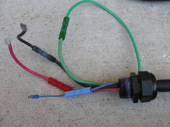 |
|
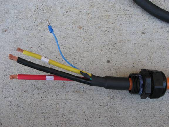
Step 5 - Move the strain relief from the old cordset to the new cordset. You may need a couple of large wrenches to loosen the compression fitting. Place the strain relief on the new cordset in a location that leaves the black and red wires just long enough to reach the relay screw terminals when the strain relief is put back in the case. The strain relief does fit over the extra insulation on the new cordset, but it’s a tight fit. You may need to completely disassemble the strain relief to get all of the parts over the extra insulation Put the new cordset / strain relief back in the chassis where the old cordset came out. Be sure to thoroughly tighten all of the large nuts on the strain relief so the cord won’t slip. Also, make sure that there’s about 3/8 of an inch of insulation removed from all of the wires at this time. |
 |
|
| Step 6 - Connect the wires from the new cordset to the relay, ground block, and pilot (Blue) wire. Be sure to pass the Red and Black wires through the current sensor (they’ll fit, but it’s a tight fit). The Black and Red wires connect to the relay in the same locations as the old Black and Red wires were connected. The Yellow/Green wire connects to the grounding block where the old Green wire was connected. The Blue wire connects to the Blue wire from the circuit board. You can use a crimp connector, a wire nut, or you can solder and insulate the Blue wire (your choice, just be sure it’s securely connected and insulated). Be sure to tighten each of the large screws down securely. | 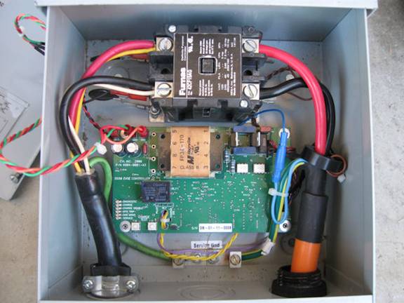 |
|
Step 7 - Put the cover back on, then turn on the power and test the charging station. |
 |
|
Remember that the charging station will not turn on unless it “sees” the appropriate diode/resistor combination between the pilot lead and the ground lead on the connector. These steps, in general, may be used in replacing the connector/cordset on other models of charging equipment that originally had the Avcon connector and originally met the 2001 J1772 standards. The wire colors are generally the same on the new cordsets with the exception of the ground which is now usually Green/Yellow instead of solid Green. “For best results, use only recycled American Electrons in your E.V.” =Photos and Text by Scott Cornell = |
||
